125 Years ( Zion-Memorial United Church circa 1888 )
https://duckduckgo.com/?q=c%3A%2Fent&t=ffab&atb=v108-3&ia=web
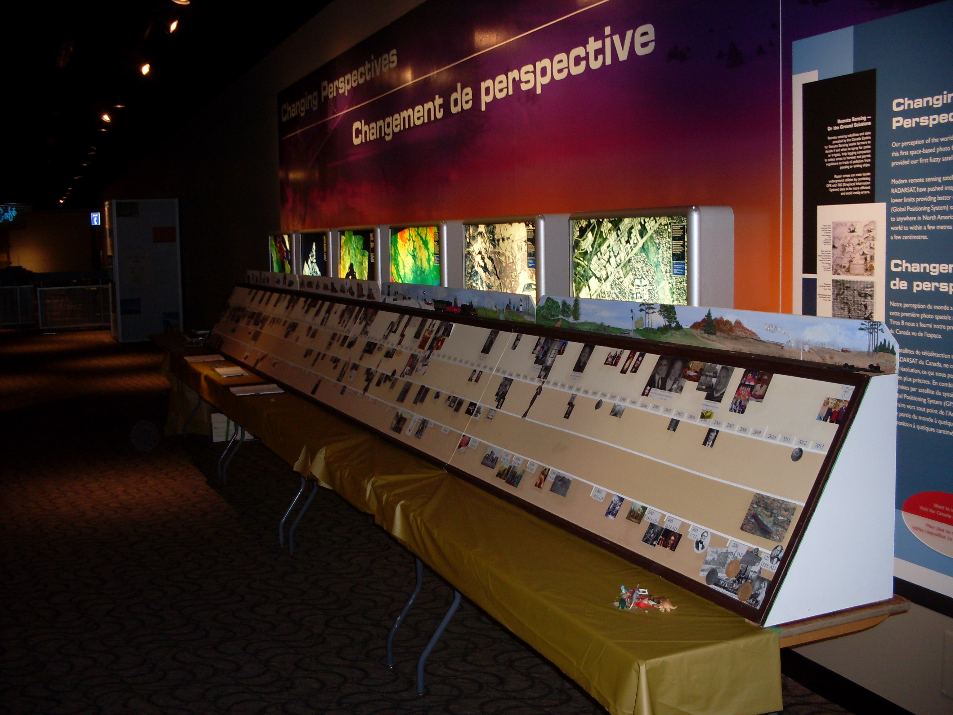
For the church 125th anniversary in 2012 I helped built a 24ft display with three rows of images covering the years from 1888 to show parallel histories of the church, the Town and the World. i.e. they were building the Panama Canal about the time the church was going up. A forth row at the bottom covered creation all the way back 13 billion years, or thereabouts. The latter was done using a logarithmic scale. Along the top I ran two HO tracks infront of a small diorama. My main interest was of course designing some electronics to run two trains with a Raspberry Pi controller. This involved sensors under the track, four speakers for sound and the odd LED. The display component was pretty much complete for the May 2012 anniversary however the electronics wasn't fully functional until the Ottawa Maker Faire in August. Before that it spent a quiet month at the town Library.
 Dial D-for-Diesel
Sometime in 2014 I was asked to look at an old HO layout built by the late Tony Percy in the Carleton Place Train Station in Carleton Place when it became a kindergarten. The East end of the building is now (2015) the CP Chamber of Commerce. What was wanted were two simple controllers to run two separate tracks, what they got was a Pi Train Interface (piti) with an old telephone dial as the input device. This was done with very little modification to the original interface as it already included a a serial current loop and the telephone pulse works quite nicely at 110 baud. e.g. (4) = @@@@.
The operation is based on a short dial sequence having assigned the dial digits as follows:
- Test
- C Carleton Place (station)
- D Diesel (inside track) [ 0x ] laps
- G Go
- L Linger at the station [ 0x ] seconds
- N Snedden's Mills ( a stop near Blakeney )
- S Steam [ 0x ] laps
- V Volume [ 0x ] e.g. x * 10%
- W Waba Siding ( a stopNorth of Pakenham )
- 0 Number e.g. [ 0x ]
Pi Train Interface Software
 My first Raspberry Pi was a model-B and fortunately I
received a second one
for Christmas so I could do some development at home while the first
was doing it's bit in 'Chambers'. I wrote the code in C because
the Pi Raspbian operating system comes with the compiler and
Gordon Henderson has written a GPIO library, wiringPi giving interrupt and PWM
support. To play sounds I use system calls to 'aplay'
with short wav files which I edited in Audacity for the left and right
speakers. A relay on the audio lines selects two more speakers.
My first Raspberry Pi was a model-B and fortunately I
received a second one
for Christmas so I could do some development at home while the first
was doing it's bit in 'Chambers'. I wrote the code in C because
the Pi Raspbian operating system comes with the compiler and
Gordon Henderson has written a GPIO library, wiringPi giving interrupt and PWM
support. To play sounds I use system calls to 'aplay'
with short wav files which I edited in Audacity for the left and right
speakers. A relay on the audio lines selects two more speakers.There is a block diagram and source code available in the source directories.
Pi Train Interface Hardware
 The
main component of the interface is an L298 dual H-driver.
Unfortunately the present circuit only allows one train at a time to be
run, this is not however a limitation of the L298. I originally
used the pulse width modulation (PWM) line that was already assigned to
sound and had the interesting side effect of playing sounds on a
train engine. WiringPi would allow two software PWM lines but
that's not where we are at! The drive circuit also has two
sensing
resistors so if there is excess current to the track a feedback loop
disables power.
The
main component of the interface is an L298 dual H-driver.
Unfortunately the present circuit only allows one train at a time to be
run, this is not however a limitation of the L298. I originally
used the pulse width modulation (PWM) line that was already assigned to
sound and had the interesting side effect of playing sounds on a
train engine. WiringPi would allow two software PWM lines but
that's not where we are at! The drive circuit also has two
sensing
resistors so if there is excess current to the track a feedback loop
disables power.The six sense circuits use Hall Effect devices fed into 74LS14 inverters and a 3K3/4K7 resistor divider down to 3.3V for the Pi. I used latching Hall devices to reduce the noise but it does mean using North & South magnets under each train.
The original design was going to use a Teletype as the controller but it's 'implementation' was delayed. The same current loop circuit, however, is now used to read a Normally Closed contact from inside the telephone dial via one of the optocouplers.
The final bit of circuitry is a small relay driver to switch the stereo input line to two stereo output lines. This now runs two PC speaker pairs.
Simple Dial Interface
For testing the telephone dial input on the second Pi I used a 10K pulldown resistor across pins-9(GND) and 10(RxD) on the Pi GPIO, and wired the dial contacts from pin-10 to pin-1(3.3V). My telephone dial pulse gives a 65ms open which at 110 baud is approximately 7 low bits. Removing the start bit, six data bits are 1000000 or "@". Ignoring parity, the software just takes any character from "@" up as a pulse. A North American telephone gives 10 pulses for a zero. (NOTE: the 9.09 ms 20mA start bit is what originally released the brake on the teletype drive)
Headless
With only a telphone dial for input the Pi has to start up automatically skipping the logon. To execute the latter I added "-a" to the tty0 line in /etc/inittab e.g. "1:2345:respawn:/sbin/getty -a pi --noclear 38400 tty1" or some such. Don't think for one minute I know what any of this means, I basically spent weeks searching the RaspberryPi forums To run the program I have a script called from .bashrc using ". /home/pi/rpiti". I also read you should HALT the Pi before you turn it OFF. My foolish scheme for this is to use a special dial string which closes the program and return codes 3 to HALT and 2 for TERMINAL. i.e. if I have a terminal attached I likely want to stick around. While I have taken screen, keyboard and mouse down to 'the Chambers' I generally now just bring along my laptop and plug it into the Ethernet port.
So the rpiti script checks to see if a mouse is attached (with screen and keyboard maybe), checks if you are logged on via Ethernet, and otherwise, if on tty1, it set up a static IP and runs piti. When piti terminates the return code is checked to initiate a HALT but only after a 5 sec timeout giving an operator time to interrupt. You probably can't get there from here but I was just trying to cover all the bases.
piti-II
While there were a few GPIO lines left over on the Pi I wanted to drive some status LEDs and a few more on the train layout. The second piti board uses the 'Pi I2C interface to drive two MCM23017 16-bit GPIOs and a DS1337 clock, both on a 3.3V rail. This gives me 32-bits to read/write and a time-of-day which the 'Pi lacks. In addition I added two 12V telephone circuits, a simple audio amplifier to drive the handset and a pulse generator to ring the bell. The bell circuit uses one GPIO line to trigger a CD4541 timer and a couple of 555s to drive 12V 20Hz out-of-phase pulses to the bell. I added a small transformer inside the telephone to up the voltage. I also wired a GPIO input from the OF-HOOK contacts inside the telephone.
Railroad Crossing Lamp
 After
the Town tracks were removed in 2012 the Town and Heritage Museum
received a
few railroad artifacts which included lights from the railroad
crossings. The idea of making them flash was bandied around so
here is what I did. Fortunately the bulb receptacle is a standard
bayonet found at Canadian Tire so I could store the original 14V bulb
(now an artifact) and replace it with a 12V car bulb. The circuit
uses a CD4541 timer which will run on up to 20V and divide the clock by
up to 65536 (2^16). Ideal for a two second cycle from 13KHz or
thereabouts. The power comes from a small 12VDC converter.
After
the Town tracks were removed in 2012 the Town and Heritage Museum
received a
few railroad artifacts which included lights from the railroad
crossings. The idea of making them flash was bandied around so
here is what I did. Fortunately the bulb receptacle is a standard
bayonet found at Canadian Tire so I could store the original 14V bulb
(now an artifact) and replace it with a 12V car bulb. The circuit
uses a CD4541 timer which will run on up to 20V and divide the clock by
up to 65536 (2^16). Ideal for a two second cycle from 13KHz or
thereabouts. The power comes from a small 12VDC converter.