September 2011 coming home from a long trip, a multi-day cool spell
(5.5 deg.
C) had numb fingers despite thinsulate gauntlets. This got me thinking
about grip heaters. I've never much liked the kind that go under or
over the grips, particularly that the wiring rotates with the throttle
and gets in the way of the throttle lock.
 Ordered some bits and pieces from eBay to fabricate grip heaters
internal
to our hollow bars. The Concours bars are aluminum, so they
conduct heat nicely. I thought this idea was original, but it seems
the concept is already established for motorcycles and
snowmobiles (Symtec
Heat Demons, Polly).
Components:
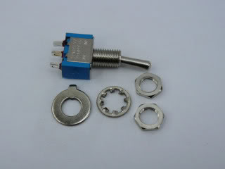
- Miniature SPDT switch (tried DPDT first).
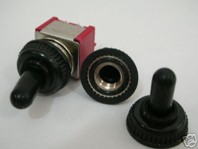
- Waterproof switch cap.
 Solid bare copper wire #20 GA
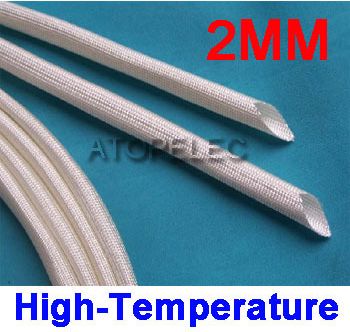
- High-temp fiberglass insulating sleeving
- Stranded #18 GA wire
- Heat shrink tubing
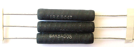
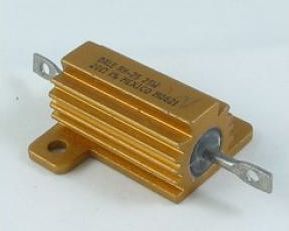
- Aluminum-clad Resistors (tried axial first)
Prototype 1
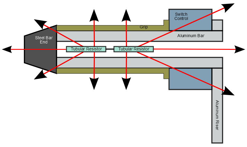
The first bench setup consisted of a couple of 7.5 ohm 10W tubular
axial lead resistors in series in a spare left handlebar, dissipating a
total of
roughtly 14W from a battery conected to a charger. The resistors had an
air
gap of maybe 1/8" to the inside of the bar, so by both conduction and
convection, heat could escape in any direction, including sideways then
out thru the switch or the bar end. The resistors got hot but not much
came out through the grips.
The heat all has to get out to the atmosphere somehow, and I intially
thought that only the power level was significant while internal
physical configuration didn't matter. But getting the heat to go where
you want is the trick, with as little as possible elsewhere.
Ideally the heat should flow directly outward from the resistor, thru
the bar grip and glove and into the hand.
Prototype 2
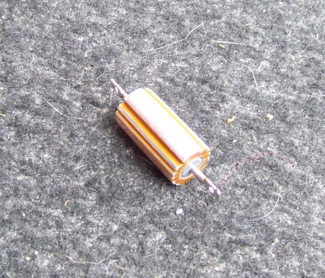 Aluminum has a much better thermal conductivity than air. So
I bought some 25W aluminum-clad resistors and filed them to just
slide/fit inside the bar, with an extra longitudinal groove to pass the
insulated return wire. It helps to file the rough edges off the
inside-bar tube weld to ease insertion.
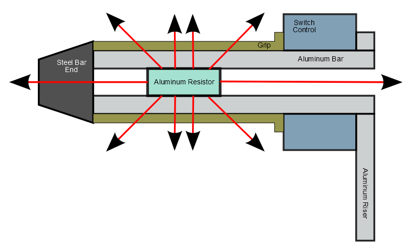
The resistors make good thermal contact to the bar, reducing the air
gap to essentially zero and this yielded much better results. A single
resistor is also a more concentrated heat
source than 2 resistors in series.
Convection transfer is largely eliminated, except from the resistor
ends. For conduction, the thermal resistance directly outward thru the
aluminum sleeve, bar and grip is lower than any sideways path through
the air to
either the switch or the bar end. There's less sideways loss, so for
the same 14W of bench test power, more heat gets to the hand.
The aluminum resistor is rated at 25W. Nothing melted or shorted. One
little irony is that these resistors run cooler because
there's a better heat path to atmosphere.
Installed Version
The installed version uses ~10 ohms on the right/throttle side, giving
19.6W, 1.4A @ 14V nominal. The left side uses ~14 ohms giving 14W, 1A.
The additional power on the right is to compensate for higher sideways
heat losses due to the thermal resistance of the throttle tube and air
gap.
Installation
 Mechanically, the tricky part is handling the return wire. It's in a
tight groove between the resistor and the bar, and has to be impervious
to high temperature. To prevent current flowing through (and ruining)
the steering head bearing, it cannot make electrical connection with
the bar.
The return lead is a few inches of #20 GA solid bare copper wire,
inside a high-temperature (good to 600 deg. C) insulating
sleeve. At the far end, heat-shrink tubing covers the resistor
connection and the insulating sleeve. At the near end, an insulated
stranded wire is soldered to the solid return lead, with heat-shrink
over the sleeve, connection and insulation. The stranded connection to
the resistor is
also heat-shrunk, and the two leads are taped together for protection.
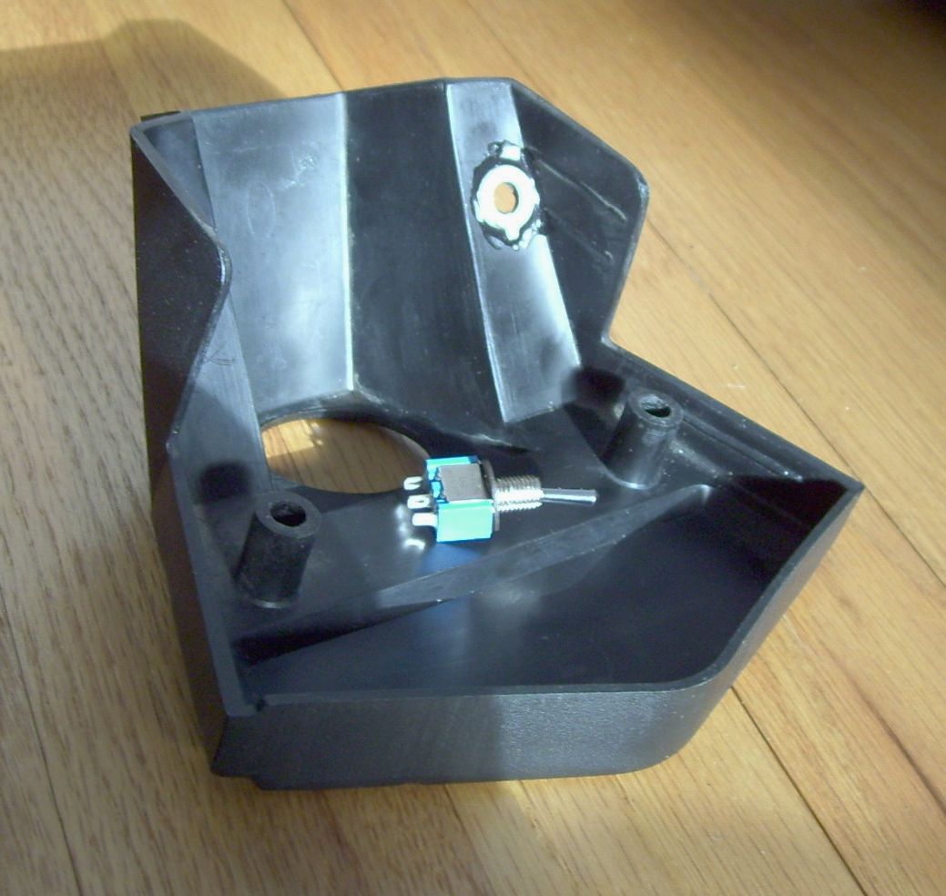
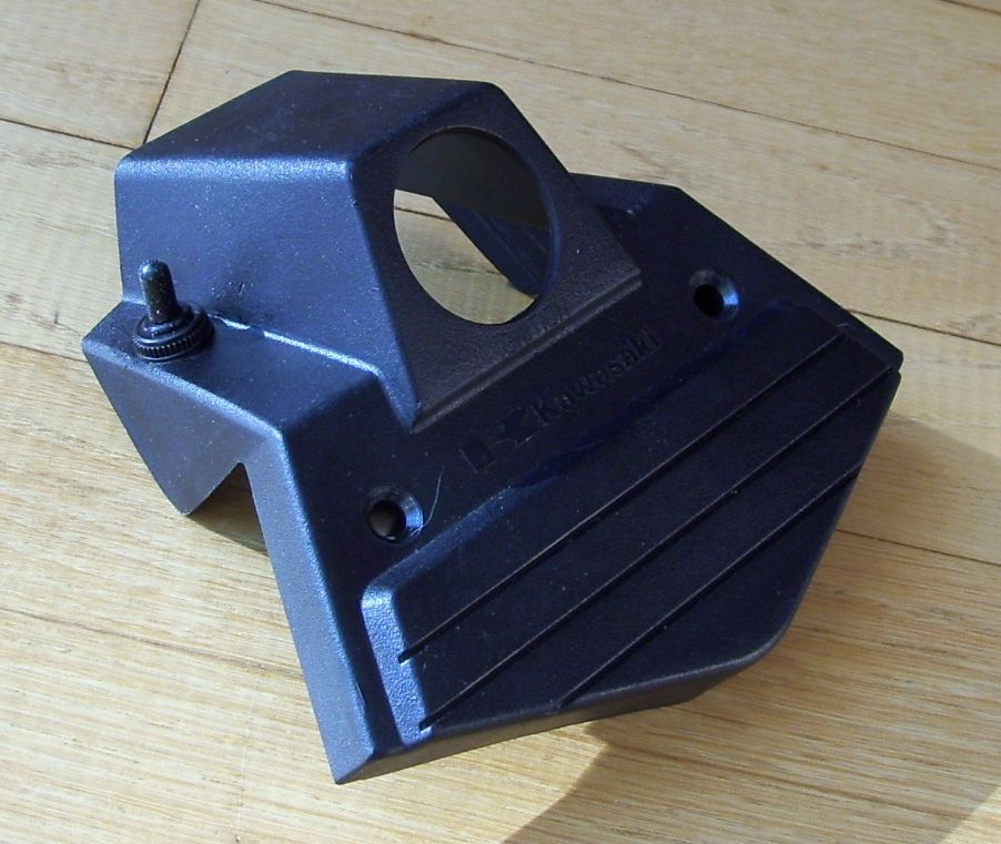 I decided to
install the on-off switch in the ignition switch bezel to
allow actuation with the left hand while the right is on
the throttle. This minimizes the number of wires which
bend when the bars are turned, only the main 12V hot and ground
wires. The DPDT switch was just a smidge too big to fit there, so I
ordered a narrower SPDT switch.
Drilled a 1/4" hole in the ignition switch bezel about 1"
forward of the back edge. Epoxied the orientation washer that
came with the switch to the underside of the bezel. Used one more 1/4"
washer as a shim under the bezel to adjust the switch height
protruding above the bezel to match the waterproof switch cover height.
The cover threads onto the switch and directly down onto the bezel top.
 Switched 12V is obtained from pin 8 of the J-Box. Routed
the 12V power source and ground wires under
  the
tank, along the cable to the ignition switch, terminating in connectors
under the top triple clamp, left side. Wired the switch under the bezel
with a connector to the 12V source under the triple clamp and
connectors to deliver 12V to the heaters.
Drilled 3/16" holes in the plastic inside bar caps for the heater
external
leads. A dab of RTV on the wires to keep water out. Stuffed a bit of
fiberglass into the bar at each end of the resistors to control
convection losses and keep the heat focused on the grip area.
Routed the heater wires immediately forward, then outwards under the
brake/clutch switch, down the outside of the bar risers, then under the
upper triple tree. Negative leads connect to ground wire connectors
under
the triple clamp, positive leads sneak up into the bezel connectors.
The right heater negative wire passes under the ignition guard bracket,
between the ignition switch and the top triple clamp to get to the
ground lead on the left side.
Results
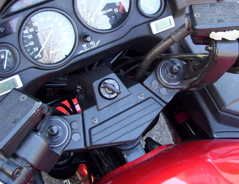 The switch is small and the cover black, doesn't spoil the stock
look. Most of the wiring is hidden, you can just see the wire
poking out the inside bar ends.
For me, hand discomfort starts around 5 deg. C and below. Got things
ready in the cold garage over the winter for a test ride in
the spring. First ride of the season was a Mar. 27/2012 evening ride around
Ottawa at 3 deg. C., deliberately using normal (thin) riding
gloves rather than (thick) insulated gauntlets.
The heat effect is warmth rather than sizzling, just enough to
reduce the pain in the fingers. Because of the aluminum bar mass, the
heat takes a while to become noticeable. If it's cold enough for
heaters to be necessary, they can stay on all the time - no need
for a variable controller.
Nov. 2012 Update
Well, November was 'good' here in Ottawa in the sense that the roads
were dry and the temperatures hovered around +2 deg. C., so I had
plenty of chances to use the grip heaters. With 14W on the left and 20W
on the right, the left would warm up more quickly (more direct
heat path) and the right more slowly (trickling through both the
throttle tube and the grip). However, after a few miles, the right
became hotter than the left. Still not so hot that I had any urge to turn
off the power. And my hands decided that they preferred hotter to not so
hot.
So a modification is planned. I'm changing the left resistance to 10
ohms to give the same 20W power as the right. The resistor has been
ordered and received, installation planned for over the winter.
Fortunately, most of the work can be done in the warm basement instead
of the freezing garage.
 Solid bare copper wire #20 GA

 Solid bare copper wire #20 GA
 Aluminum has a much better thermal conductivity than air. So
I bought some 25W aluminum-clad resistors and filed them to just
slide/fit inside the bar, with an extra longitudinal groove to pass the
insulated return wire. It helps to file the rough edges off the
inside-bar tube weld to ease insertion.
 Mechanically, the tricky part is handling the return wire. It's in a
tight groove between the resistor and the bar, and has to be impervious
to high temperature. To prevent current flowing through (and ruining)
the steering head bearing, it cannot make electrical connection with
the bar.
 I decided to
install the on-off switch in the ignition switch bezel to
allow actuation with the left hand while the right is on
the throttle. This minimizes the number of wires which
bend when the bars are turned, only the main 12V hot and ground
wires. The DPDT switch was just a smidge too big to fit there, so I
ordered a narrower SPDT switch.
 Switched 12V is obtained from pin 8 of the J-Box. Routed
the 12V power source and ground wires under
  the
tank, along the cable to the ignition switch, terminating in connectors
under the top triple clamp, left side. Wired the switch under the bezel
with a connector to the 12V source under the triple clamp and
connectors to deliver 12V to the heaters.
  The switch is small and the cover black, doesn't spoil the stock
look. Most of the wiring is hidden, you can just see the wire
poking out the inside bar ends.