 A permanent magnet alternator consists of a
number of magnets on a
rotor whirling around outside a stator. On the SV650S, the stator
is connected to a rectifier/shunt regulator to convert the AC to DC
  and control
the
voltage supplied to the battery and bike components, e.g., ignition,
lights, etc. A feature
of the shunt regulator design is that the stator delivers its full
output (20-odd Amps) all the time, and whatever power is not used by
the bike components is dissipated as heat in the regulator or
stator.
The regulator gets hot and fails rapidly. The stator gets hot, the
insulation chars, and it eventually shorts to ground and ceases to work
properly. This latter struck on three separate occasions on a Yamaha
XZ550 Vision with the same cursed design. A couple of times this was
far away from home, so I learned how to travel with lights
disconnected and bump starting.
Even when it's working as designed, a shunt regulator doesn't
do a
great job of charging up the battery. On the SV650 I was observing 13.7
volts at
idle, dropping to 13.1 volts at a few thousand RPM.
 Various
approaches have been tried on the SV650 to circumvent these
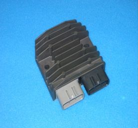
problems. The newest and most promising is the
series regulator
which interrupts the AC input to control the DC output
voltage. The current in both the stator and the regulator is reduced to
only what is needed by the bike components and battery charging. So I
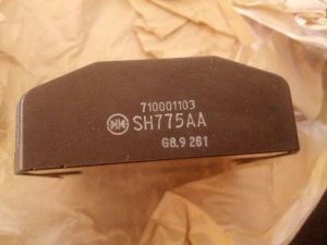
purchased a used Shindengen SH775AA part # 710001103 via eBay which
started
life on a Sea Doo Challenger. Also known as a Polaris #
4012941, possibly others part numbers.
Mounting
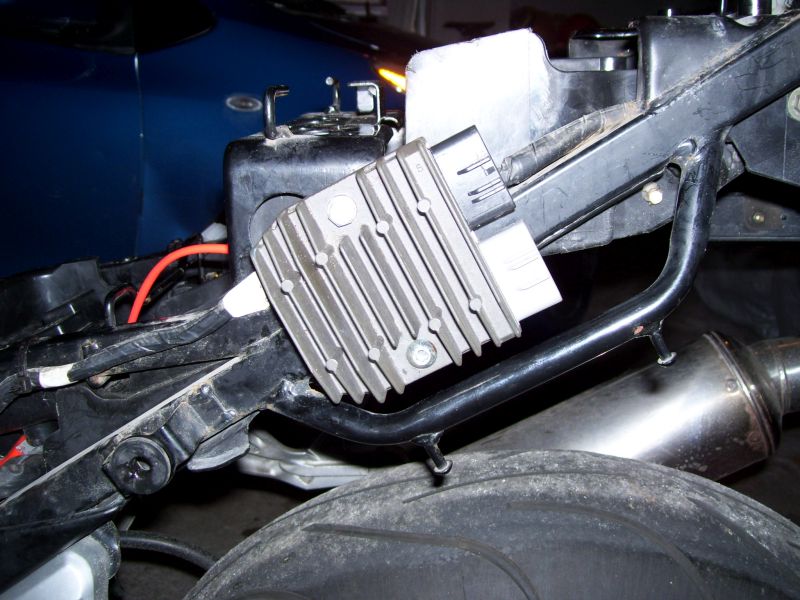
It's a bit bigger than the stock regulator and would not fit in the
same location on the right of the bike, even though the bolt hole
spacing was the same. However good fortune smiled on me - there was
room to mount it at an angle on the left side. The top is
secured by a
bolt
into an existing 6mm threaded hole, with a 1/4" spacer behind the
reg/rect. The bottom is fastened to a bracket held by a
mudguard mount bolt to orient the regulator parallel to the frame
member. Then, everything snuggles nicely under the rear cowling.
Wiring
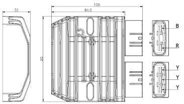
The little extension
with the 3 yellow wires was sacrificed, chopped it
in half and spliced the male connector to the 16GA wiring for the AC
input, used 14 GA for the DC output leads. For frugality reasons, I
initially opted for spade clips rather than fancy connectors in case
things didn't work out.
Results
Testing in the garage (Nov. 2014), at idle, the voltage across the
battery is 13.9 volts, at running engine speed 14.5 volts. So far looks
solid. Will have to wait for spring and the first ride to check
regulator temperature.
Temperature
After a half hour ride on a 27 deg. C. day (May 2015) in Ottawa, the regulator body was warm to the finger test, but not too hot to touch.
Connector Upgrade
Once the regulator had been
on the road for a while (July 2015), I
decided to install the proper connectors.
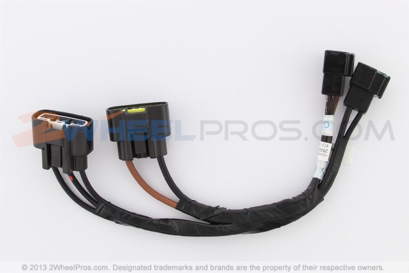
 At the regulator end, Triumph came through with a
part called a Link Lead
(T2500676) encompassing both AC and DC Furukawa connectors,
surprisingly reasonable at my local dealer. After taking apart its
wiring harness and discarding unnecessary connectors, the triple
connector leads were spliced to the previously installed regulator wiring,
soldered and heat shrunk. Looks much more professional now and might
even keep out water.
To
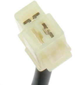
connect at the wiring harness end for the DC output, I cut the connector off
the useless shunt regulator and spliced it to the wiring from the regulator. Now
have legitimate connectors at each end, not just the flimsy spade clips.
 A permanent magnet alternator consists of a
number of magnets on a
rotor whirling around outside a stator. On the SV650S, the stator
is connected to a rectifier/shunt regulator to convert the AC to DC
  Various
approaches have been tried on the SV650 to circumvent these
problems. The newest and most promising is the
series regulator
which interrupts the AC input to control the DC output
voltage. The current in both the stator and the regulator is reduced to
only what is needed by the bike components and battery charging. So I
purchased a used Shindengen SH775AA part # 710001103 via eBay which
started
life on a Sea Doo Challenger. Also known as a Polaris #
4012941, possibly others part numbers.